
Font size 

Advanced Studies

Accl. Operations

Past Accl. Operations
Accelerator R&D

Theoretical Research
Archives
〜SIMULTANEOUS TOP-UP OPERATION OF THREE DIFFERENT RINGS IN KEK INJECTORLINAC〜
1. What is the injector linac?
In KEK Tsukuba campus, the four storage rings are operated for various user experiment. KEKB1electron/positron ring (3 km circumference) is utilized for the high energy physics research. PF2(187 m circumference) and PF-AR3(377 m circumference) rings are the powerfull devices for the material and life science researches. KEK injector linac4 is a 600-m-long linear accelerator, and provides the electron and positron beams of different energy for the four independent rings <Fig. 1>. At the beam switchyard located in most downstream of linac, the beam with different property is delivered toward each ring as shown in <Fig. 2>.
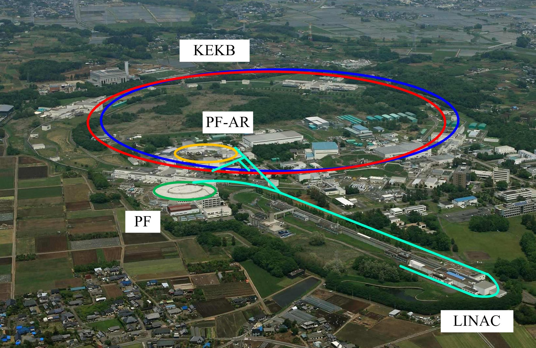 |
| <Figure 1> KEK injector linac and four storage rings. |
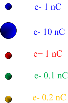
| <Figure 2> Beam switchyard at most downstream of linac. |
1) KEK B-factory
2) Photon Factory
3) Photon Factory Advanced Ring for pulse X-rays
4) LINear ACcelerator
2. Beam injection
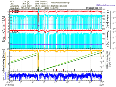
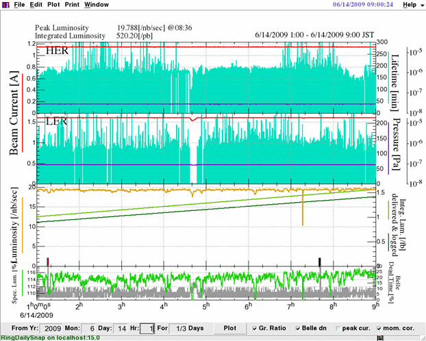
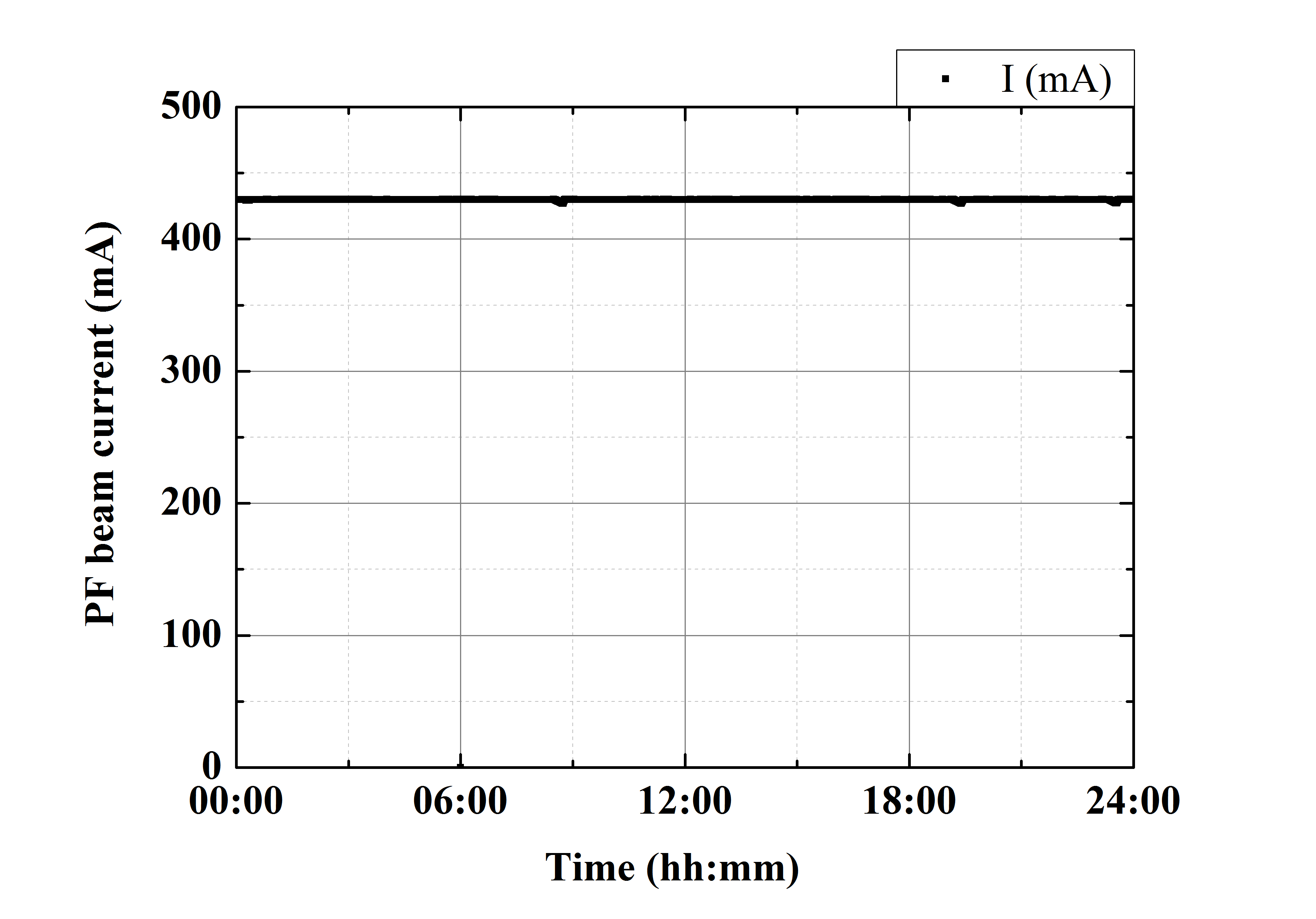
Since there is only one injector linac, the common injector linac should provides the beams with different properties for the four different rings.The required injection beam energy and amount of charge are different for each ring as shown in Table 1. In order to increase the beam injection efficiency, the optimized linac parameter should be utilized for the control of each beam injection. The linac parameter includes the electromagnet (more than 500) and timing signal (more than 200) settings. The maximum beam repetition of KEK linac is 50 Hz (20 ms interval). However, the linac parameter switching is required before the beam injection of different ring. Sometimes, such parameter switching took more than 5 minutes <Fig. 3>. <Figure 4> shows the typical one day operation of KEKB in May 2000. Here, the beam injection was carried out in every 90 minutes. After the beam injection, the stored beam current monotonically decreases until next injection, and eventually it results in decreasing also the luminosity5. The luminosity is a figure of merit for collider type accelerator. For getting the higher experimental efficiency (which brings a large amount of experimental data), we have to keep the higher luminosity as long as possible. <Figure 5> shows the stored current of PF ring (24 hours). The typical beam injection for PF and PF-AR is twice daily on scheduled time. The decreasing of stored current in light source also causes the reduction of synchrotron radiation intensity, eventually it decreases the experimental efficiency. In 2005, we started the continuous injection of KEKB by changing the linac parameter in every several minutes as shown in <Fig. 6>. Although the integrated luminosity was improved in comparison with original injection scheme, much more stability of stored current was strongly required for increasing the beam tuning efficiency and integrated luminosity. At the same time, the top-up injection6 for PF ring was also strongly demanded from experimental user community.
5) KEKB archived the world record of peak and total integrated luminosity.
6) Beam operation of keeping stored current by continuous beam injection. also called "top-off injection".
<Table 1> Injection beam energy and charge
| Energy (GeV*) | Charge (nC**) | |
| KEKB electron | 8 | 1 |
| KEKB positron | 3.5 | 1*** |
| PF | 2.5 | 0.1 |
| PF-AR**** | 3 | 0.2 |
*) G (giga) denotes 109 eV (electron volt) is a unit representing energy. 8 GeV is corresponding to 8000000000 eV.
**) n (nano) denotes 10-9, C (coulomb) is a unit representing the amount of charge. The electron
beam of 1 nC contains about 6200000000 electrons.
***) Primary beam for positron production is 10 nC electron beam with 3.7 GeV.
****) PF-AR ring accelerates injected 3 GeV electron beam up to 6.5 GeV for user experiment.
 |
 |
| <Figure 3> Schematic drawing of ordinary beam operation in linac. |
KEKB-HER (High Energy Ring): KEKB electron ring.
KEKB-LER (Low Energy Ring): KEKB positron ring.
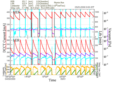 |
| <Figure 4> Stored current and luminosity of KEKB (24 hours) electron (top), positron (middle) beam current, and luminosity (bottom). |
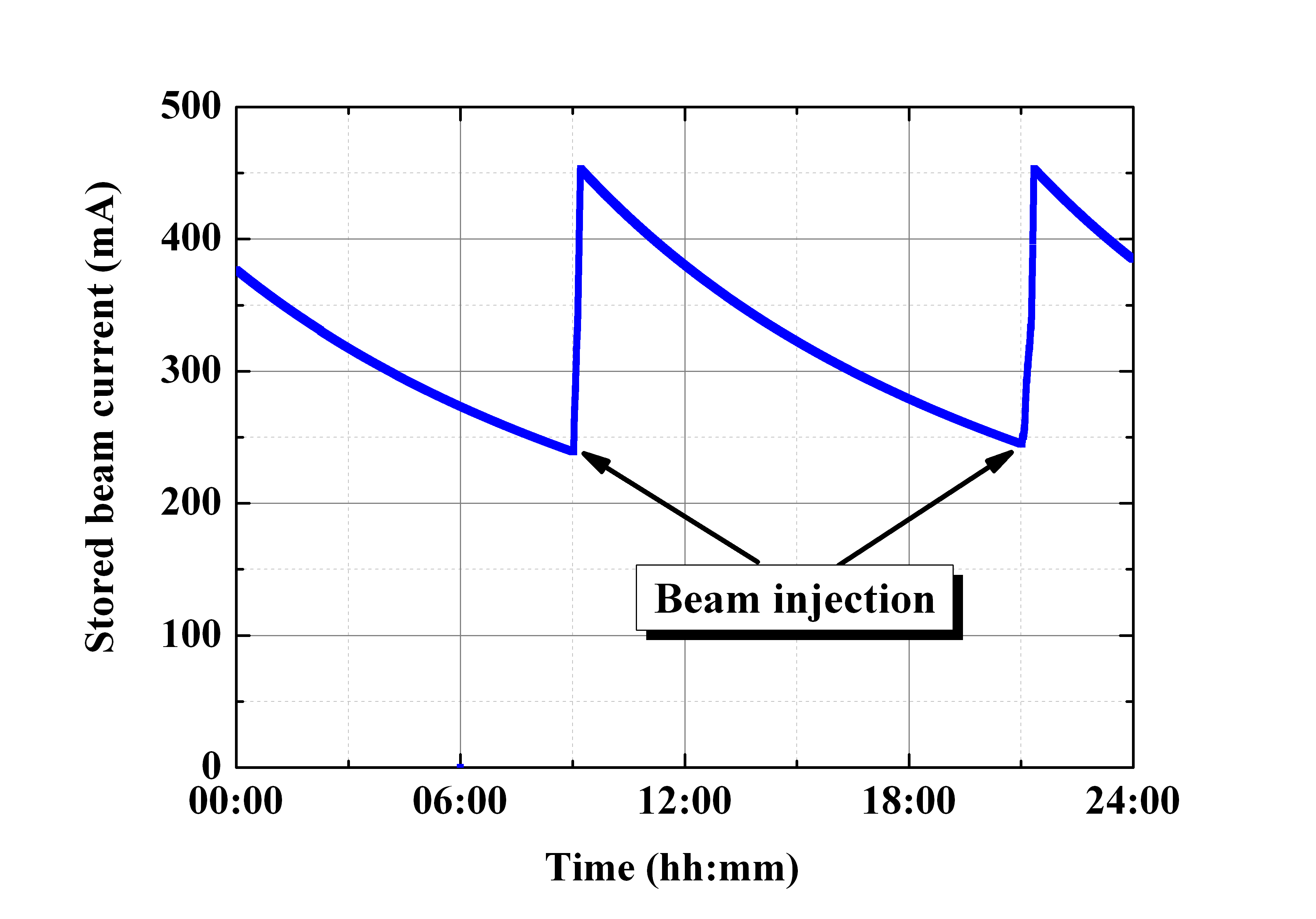 |
| <Figure 5> Stored current of PF ring (24 hours). |
 |
| <Figure 6> Stored current and luminosity of KEKB during continuous injection (24 hours). |
3. Injector linac upgrade
For these reasons, we have started the injector upgrade project aiming at the simultaneous
top-up injection for the three independent rings (KEKB electron, KEKB positron, and PF) in May 2004.
At first, it seemed a big challenge. In every 50 Hz (20 ms interval), we have to accelerate the beam with different amount of charge up to different energy, and then inject them into different rings.
Fast switching of linac parameters
Towards the simultaneous top-up injection, the linac parameter should be changed in every 20 ms. In KEK linac, the high power rf voltage from a pulsed klystron with 4 µs duration is utilized for the electron/positron beam acceleration. The velocity of beam and rf phase are synchronized as shown in <Fig. 7>. The optimized rf phase with respect to beam depends on the amount of charge and sing of electric charge (namely, electron or positron). The fast phase control of low level rf driving a high power klystron was adopted to adjust rf phase. In addition, the klystron output timing with respect to the beams can be quickly controlled for changing the fast beam energy controll.
At the beginning of this project, the fast changing of the magnet power supply setting seemed to be difficult. In KEK linac, almost all power supplies for electromagnets are the direct current (DC) type one. The replacing all of existing power supplies by the pulsed type one seems to be not feasible because of large cost. After then, we were thinking about the solution "Is there any possible magnetic field setting which is available for the beam acceleration of different energy?" The results of computer simulation and preliminary beam study have brought us the feasible solution. The injection beam energy difference between KEKB electron (8 GeV) and PF ring
(2.5 GeV) is most large for the linac operation. <Figure 8> shows the energy variation of each injection beam along linac in the
new scheme. Here, the PF injection beam is accelerated up to more than the required energy for injection. After then, the beam is transported without any acceleration in middle of linac. Finally, the beam is decelerated down to the 2.5 GeV in the end of linac. In the upstream area of linac, this scheme can enlarge the common energy area in upstream of linac, and it is feasible for you to use the common electromagnet settings. In the downstream area, we use the happy-medium settings for all beams instead of the optimized one for each beam property.
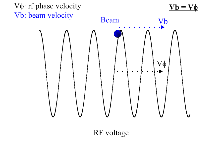 |
| <Figure 7> Beam acceleration by RF voltage. |
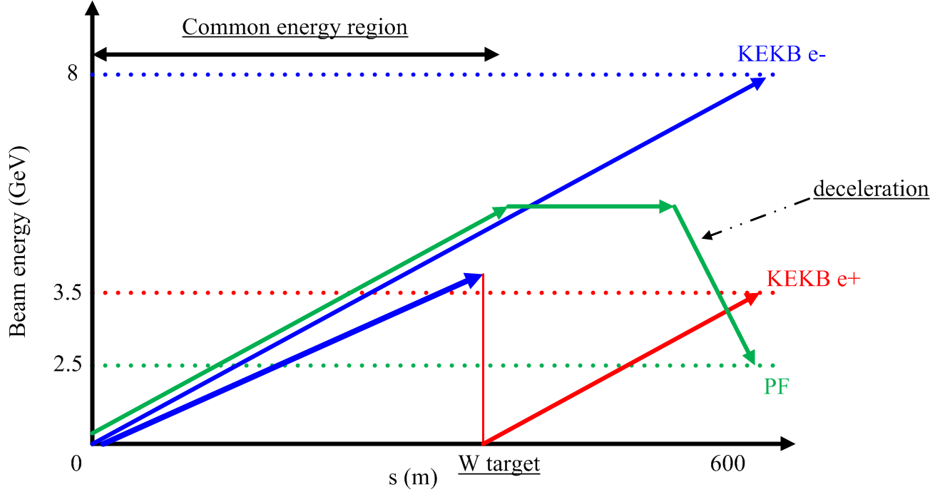 |
| <Figure 8> Energy of each injection beam along 600-m-long linac. Beam energy vs. distance from electron gun. |
Event timing system
The fast beam energy control needs to switch the timing and rf phase of klystron in every 20 ms. We have adopted the event based system as a new timing control system since the switching performance of old system is about several second. The new event timing system consists of a event generator and receiver based on VME64x-bus6 as shown in <Fig. 9>. The event generator and receiver are connected by start topology via optical fiber, and the receiver can output the timing signal corresponding to the event id set on the generator board. Associating each event id with specific timing settings, the beam energy and rf phase can be easily changed to the optimized setting in every 20 ms by switching event id on the generator. One event generator and twenty one receivers have been installed for the fast timing control.
In addition, several VME-based DAC7 modules have been also installed for the fast control of rf phase.
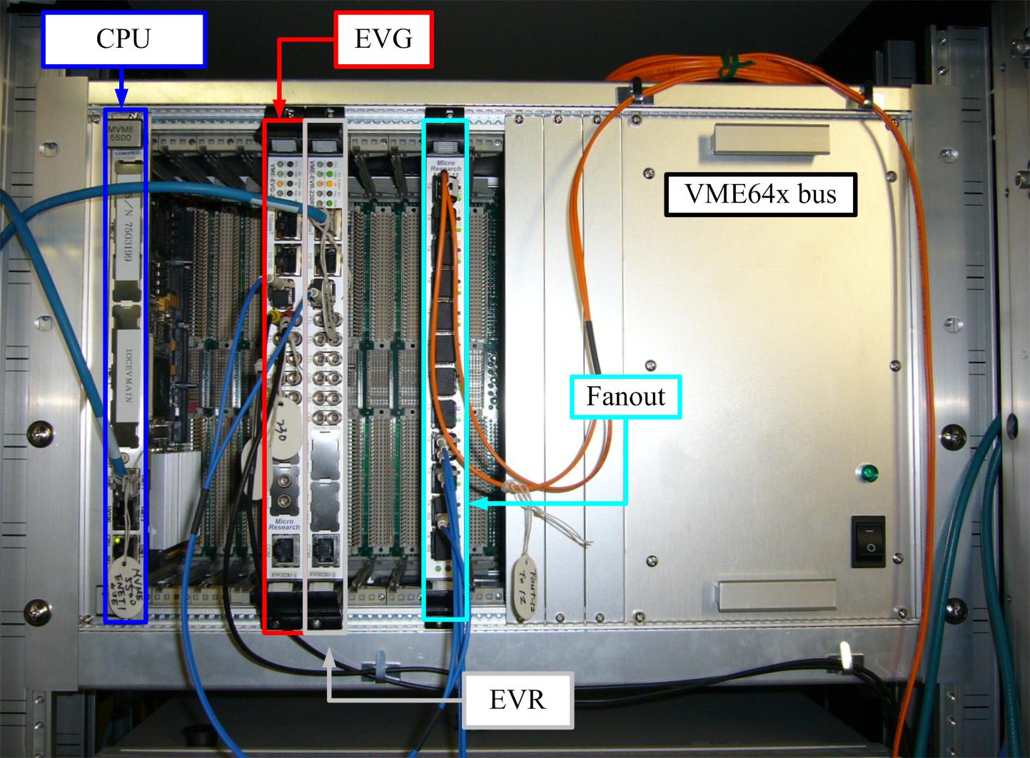 |
| <Figure 9> Photograph of event timing system |
6) A computer bus standard. In the accelerator control system, VMEbus based
system is widely used in many facilities.
7) Digital-to-Analog Converter: A device that converts a digital data to an analog signal (current, voltage, or electric charge). In KEK linac, many DAC modules are utilized for local device control like a magnet power supply and rf phase shifter.
New PF-BT and pulsed bending magnet
The parameter switching for PF injection required more than 5 minutes since the control of ECS (Energy Compression System) magnet setting took a several minutes. The beam transport (BT) is a beam line between linac and each ring without any beam acceleration, and the old PF-BT branched off at downstream of ECS magnet. After the construction of new PF-BT as shown in <Fig. 10>, it has been unnecessary to change the ECS setting even for PF injection since the new pulsed bending magnet has been installed in upstream of ECS as shown in <Fig. 11>.
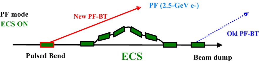 |
| <Figure 10> New PF-BT and ECS bending magnets. |
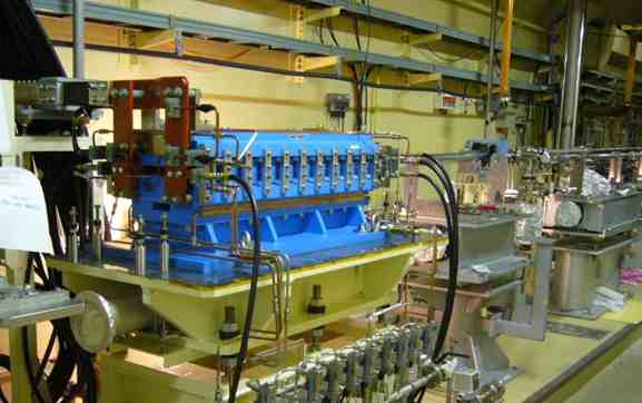 |
| <Figure 11> Photograph of pulsed bending magnet. |
New positron production target with a hole and pulsed steering magnet
For the positron beam operation, the primary electron beam with high intensity and energy collides with the heavy metal target, and then the electron and positron particles are obtained by the electromagnetic cascade shower. Only the positron beams are captured and accelerated up to 3.5 GeV for KEKB positron injection. In KEK linac, we use the 10 nC primary electron beam with 3.7 GeV energy, and the tungsten (W) target is utilized as a positron production target. So far, the positron target is mechanically extracted/inserted from/into the center of beamline. In the former scheme, the mechanical movement of target holder cannot be applied to the fast control. In addition, the cyclic life time of bellows could be crucial problem by frequent insertion and extraction of target holder. At the begging of this project, we considered the construction of bypass beamline. However, it seemed to be difficult because of tight space issue around the positron target. Eventually, an excellent idea has been suggested. For the new scheme, we have developed the positron target with a hole for electron beam transport as show in <Fig. 12>. Although the positron target is alwasy fixed at the inside of beamline even during the electron injection, the electron beam can be passed inside a hole by using the bumped orbit which is controlled by the pulsed steering magnets as shown in <Fig. 13>. The result of beam study shows that the beam loss of electron is negligibly small in comparison with that of the ordinary scheme as shown in <Fig. 14>.
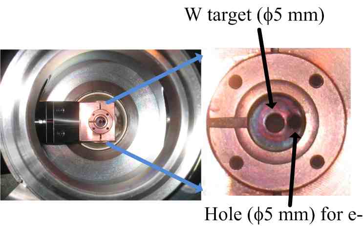 |
| <Figure 12> New positron production target (tungsten: W). |
 |
| <Figure 13> Fast switching between electron and positron beam operation. |
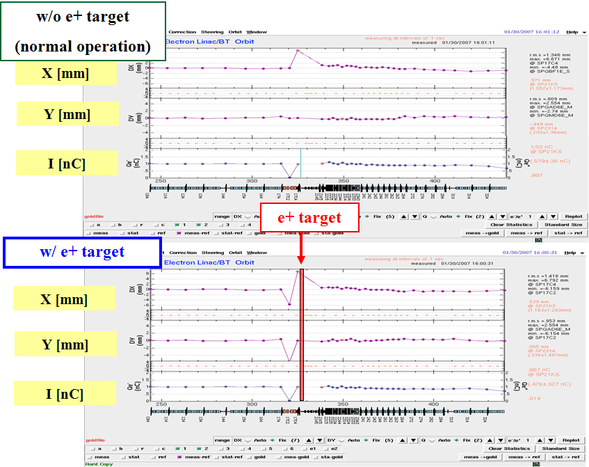 |
| <Figure 14> Beam orbit and charge by using ordinary (upper) and new scheme (bottom). |
Simultaneous top-up injection for three independent storage rings !!!
After we have developed the many subsystems and completed the various beam studies as mentioned above, the simultaneous top-up injection as a daily operation started in April 2009. The schematic drawing of simultaneous top-up injection is shown in <Fig. 15>. <Figures 16> and <17> show the stored current of KEKB and PF during simultaneou top-up, respectively. The stored current variations of KEKB and PF are less than 0.05% and 0.01%, respectively. Unfotunately, PF-AR injection is still based on the old scheme which takes a several minutes for the linac parameter switching. Because of that, the beam injection for PF-AR interrupts the simultaneous top-up operation about 15 minutes twice daily. Nobody doubt that the simultaneous top-up operation improves greatley the integrated luminosity of KEKB and the integrated brilliance of PF, even thogh such interruption still remains.
 |
|
| <Figure 15> Schematic drawing of simultaneous top-up injection for three independent rings. |
 |
| <Figure 16> Stored current and luminosity of KEKB during simultaneous top-up (24 hours). |
 |
| <Figure 17> Stored current of PF ring during simultaneous top-up (24 hours). |
4. Summary and future plan
After the many developments and beam studies (construction of the new PF-BT, event timing system, pulsed bending magnet/power supply, long-racetrack ceramic chamber, new positron target, radiation safety system upgrade, etc...), we finally archived the simultaneous top-up operation for three rings with different energy and amount of charge. The achievement of this milestone have been brought through the grate effort of all members of linac, PF, and KEKB accelerator groups. We starts recently the new upgrade for SuperKEKB project. The key challenges are the developments of a low-emittance RF electron gun and high efficient positron capture system. In SuperKEKB, the beam lifetime8 will become very short (one tenth lifetime of KEKB). In such case, even the several minutes interruption of SuperKEKB injection causes large deterioration of beam operation availability. In order to avoid such situation, we are planning a new scheme of simultaneous injection including PF-AR, and its detail will be reported in the future opportunity.
8) The time representing that the stored current in the ring decrease about one third. This phenomina is mainly caused by the collision between the stored beam with atoms of the residual gas, and eventually the beam loses energy and/or is deflected.
〜 Author : Accelerator Division V, Masanori Satoh 〜
| Copyright(c) 2008, HIGH ENERGY ACCELERATOR RESEARCH ORGANIZATION, KEK 1-1 Oho, Tsukuba, Ibaraki 305-0801 Japan |
|web-acc |