Start operation of the Small Electron Linear Accelerator for calibration of the Fluorescence Detector of the Telescope Array experiment
1.Ultra-high energy cosmic rays observation and the Telescope Array experiment
The Telescope Array (TA) experiment is a ultra-high energy cosmic rays (UHECRs) observation which is established in the desert area about 200 km far from Salt Lake City in Utah state, north U.S. We began the observation in April 2008. The UHECRs are the highest primary cosmic rays which have energy more than 1018 eV. However, we do not understand any fundamental features, for example the chemical composition, their generation and acceleration mechanism, and the theoretical flux limit (GZK-cutoff ).
There are more two large UHECRs observation experiments. One of them is the Pierre Auger experiment which is established in Argentina, south U.S., and began the observation in 2004. Another one is HiRes experiment which was already terminated, and the members of the collaboration join to the TA experiment. Recently our and their results are reported and the discussion of these interesting reports is quite lively.
 |
| <Fig.1>The overview of the TA experiment. The TA experiment consists of the Surface Detectors which detect the electrons, positrons and gamma-rays in a large cascade shower which is generated by the collision with UHECRs and the air molecular in the atmosphere, and the Fluorescence Detectors which detect the fluorescence photons which are emitted in the large cascade shower. |
2.The necessity of the Small Electron Linear Accelerator (ELS)
The most important theme of the UHECRs observation experiment is the precise measurement of the primary energy of the UHECRs. Nevertheless, that is one of the most difficult. The TA experiment and Auger experiment and HiRes experiment use the same method for measurement the primary energy of by using the number of the fluorescence photons which are detected by the fluorescence detector (FD). The fluorescence photons are emitted from the excited nitrogen molecular in a large cascade shower which is generated by the collision with the UHECRs and air molecular in atmosphere <Fig.2>The overview of the TA experiment. The TA experiment consists of the Surface Detectors which detect the electrons, positrons and gamma-rays in a large cascade sh. However, the systematic uncertainties of their energy scale have more than 20 %. The large uncertainties are the fluorescence yield parameters, the attenuation coefficients in atmosphere, and the calibration constants of the FD. We need a source for the end-to-end absolute energy calibration of the FD.
We proposed an innovative method for absolute energy calibration with a known energy source. That is the small electron linear accelerator (Electron Light Source ; ELS). The ELS is installed at 100 m far from the FD and the vertical accelerated beam is injected into the sky<Fig.3>. The overview of the TA experiment. The TA experiment consists of the Surface Detectors which detect the electrons, positrons and gamma-rays in a large cascade sh. The typical output power is 40 MeV ×109 e-/pulse ×0.5 Hz. Since the output energy of the accelerated beam is known value, we can estimate the energy deposit in the air. The importance is that we calibrate the response function from the energy deposit of electrons in the air to output signal of FD. Then we can calibrate the absolute energy scale by the comparison with the response of the real and the simulation. The ELS is a unique source for the absolute energy calibration for the UHECRs observations in the world.
 |
| <Fig.2>The overview of the method for the observation of UHECRs with FD. |
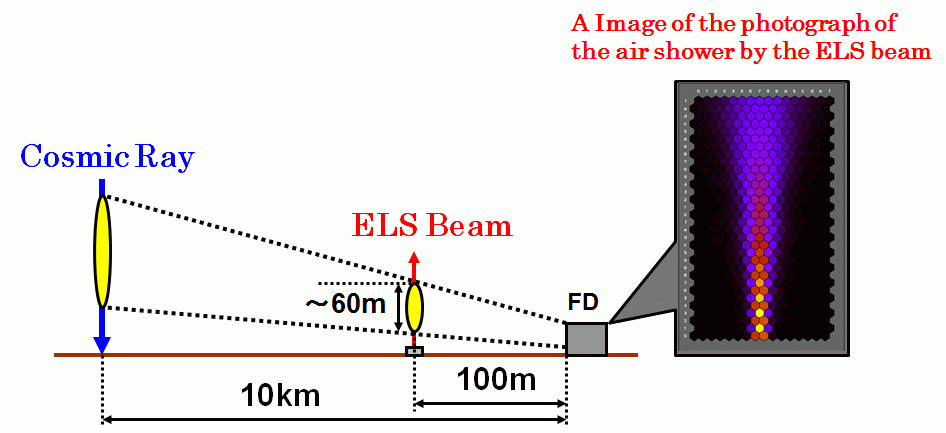 |
| <Fig.3>The overview of the absolute energy calibration for FD by using the ELS. If we ignore the attenuation of photons in the atmosphere, we can scale the total energy deposit of the electron beam in the air to the that of a UHECR which has the energy as 1020 eV. |
3.The development of the ELS
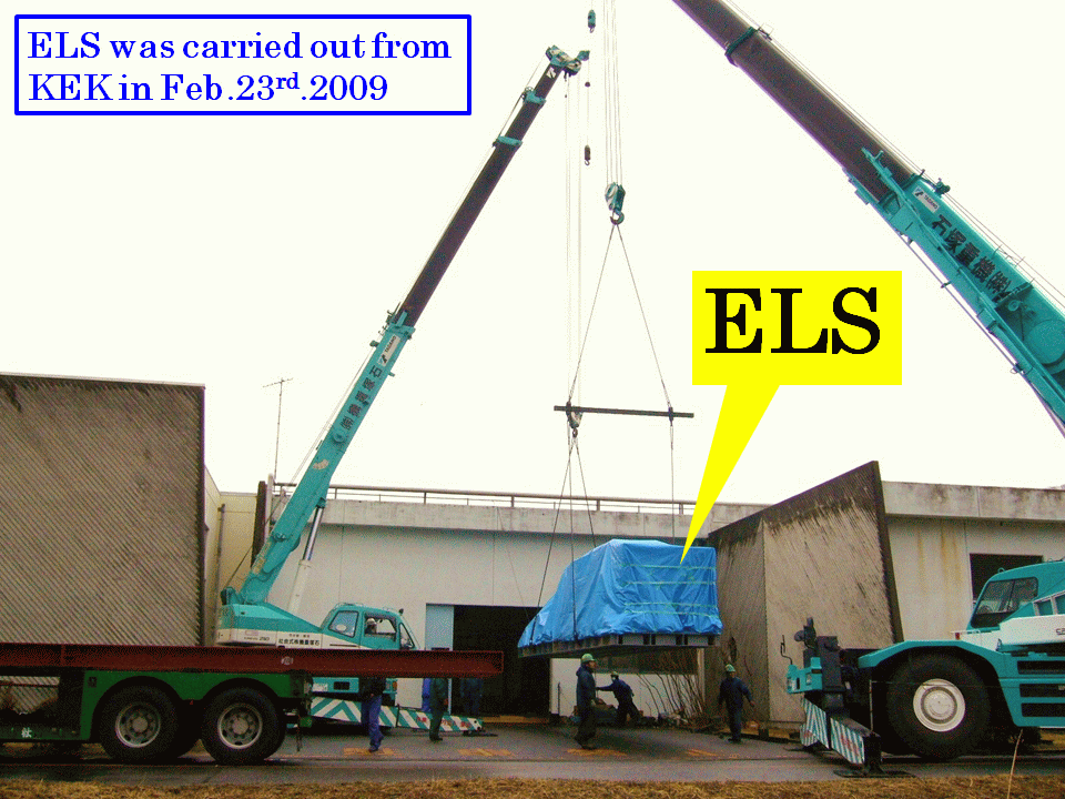
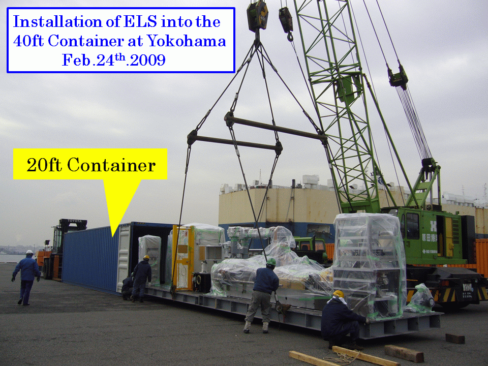
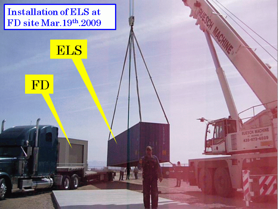
The development of the ELS was started at KEK with electron-positron injector group as collaborative research in April 2005. The important feature of the ELS is that the main components which were supplied from them were the spare devices for electron-positron injector. For example, the RF system, the waveguides, the pre-buncher and buncher tube, the main accelerator tube, and the focus magnets. It is first opportunity for them that the properties of KEK are used for cosmic ray research. We designed and constructed the accelerator unit and the cooling unit which can be installed into the 40 ft and 20 ft containers. The construction of the ELS was completed in January 2008. We began the operation the ELS at KEK for evaluation of its performance in February. The <fig.4≶ shows the schematic view of the ELS, and the <fig.5> shows the memorial photograph with KEK staffs at KEK. The ELS was carried out from there in the end of February 2009, and installation in the FD site in Utah U.S. was completed in the end of March 2009 <Fig.6, 7, 8>. At the same time a container for control room and a power generator were also installed in there.
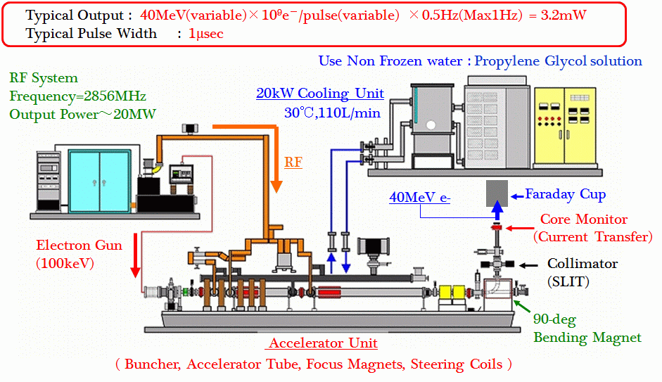 |
| <Fig.4>The schematic view of the ELS. We use the S-band RF system, one buncher tube and one 2-m main accelerator tube. The accelerated electron beam is bent to vertical direction by the 90-degree bending magnet. The electron beam is injected into the sky. |
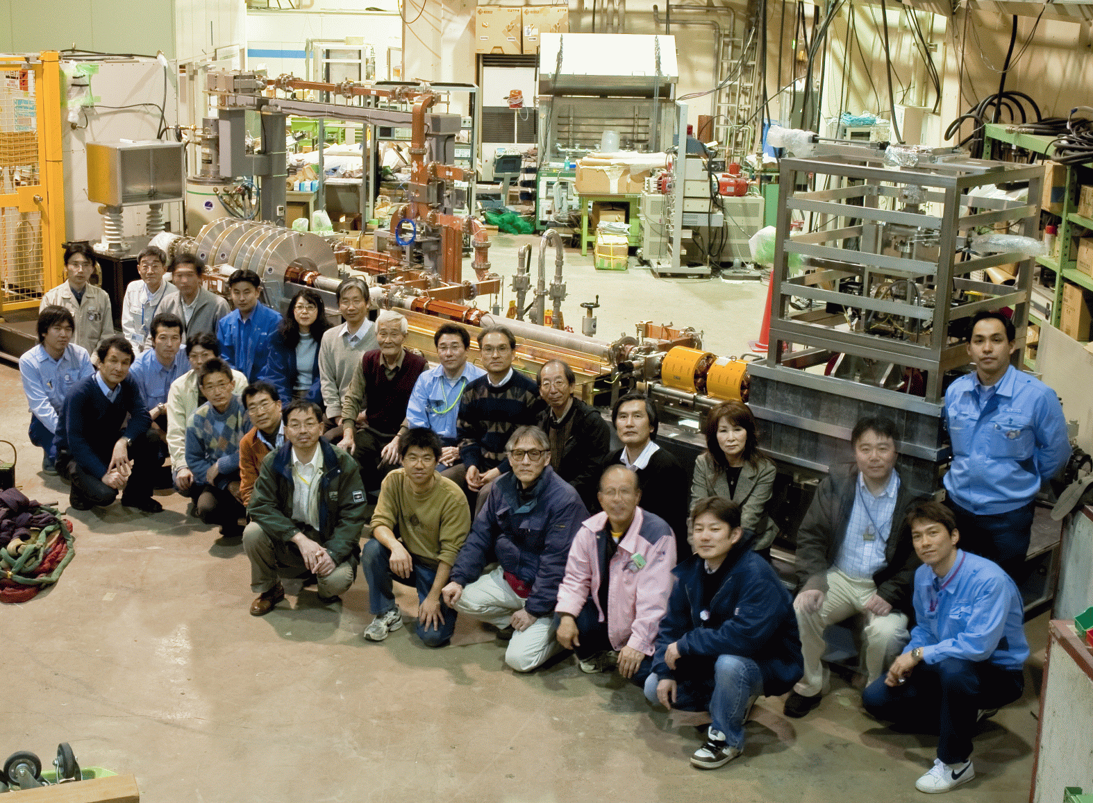 |
| <Fig.5>The memorial photograph with KEK staffs at KEK. (It was taken in 19th Feb.2009) |
<Fig.6,7,8>The photographs of shipment of the ELS from KEK and the installation in the FD site.
 |
| <Fig.6> |
 |
| <Fig.7> |
 |
| <Fig.8> |
4.The preparation for the operation of the ELS and first shot in the sky.
We stared the preparation for the operation of the ELS in April 2009 at the FD site. At first we installed the AC power cables. The installation of all of the cablings was finished in the end of September 2009. After that we started making vacuum of the electron-gun chamber and the waveguides and the beam line. There was no vacuum leak in the electron-gun chamber, while a screen monitor which is installed at the downstream of the beam line had serious vacuum leak because of a snapping apart at the welding pipe. The screen monitor was returned to KEK, and was welded. After we repaired and confirmed no vacuum leak, we re-installed it into the beam line. We took four months to fix this problem. The most serious problem was vacuum leak in the klystron. Just after the installation of the ELS in the FD site, we checked vacuum leak of the klystron by using a portable power generator, and we confirmed a vacuum leak. We needed exchange the klystron. We guess the main source of the vacuum leak problem was the vibration during the shipment from KEK to the FD site. By the way, we installed the heat insulators which the thickness is about 6 inches at the outside wall of the containers for keeping the temperature of inside the container. We constructed the remote control and monitor system for ELS system. The optical network cables were installed between the FD building and the ELS control container for communication.
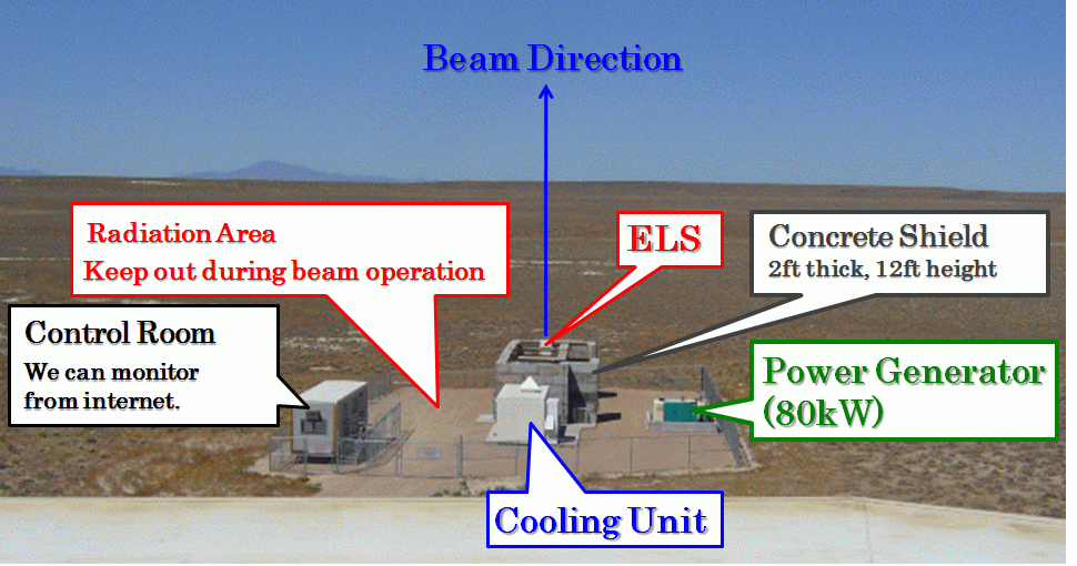
The ELS is managed by the radiation health department of university of Utah. The radiation safety officers and the responsible users were organized. We made some rules and installed some safety interlock systems for radiation and high voltage safety. We also installed the concrete blocks which the thickness is 2 ft and the height is 12 ft. We completed the radiation safety system in the end of May 2010.
We started the preparation for the beam operation in June 2010 with three expert persons in KEK, Prof. Shigeki Fukuda, Assistant Prof. Mitsuhiro Yoshida and Assistant Prof. Takashi Sugimura and one expert person from Mitsubishi-Denki system service Co., Ltd., Mr. Yasuo Imai. Until the end of June, we completed the exchanging the klystron, the RF system test, the RF aging and the electron-gun system test. We re-started the preparation in the end of August, and we turned on the accelerator beam in 1st September 2010. However since the RF aging was not enough, many discharges were happened at the inside of the accelerator tube and we needed the RF aging more one day. The first accelerated beam was detected in the next day. We confirmed the straight accelerated beam signal by using the screen monitor and current transfers. In 3rd September, we confirmed the vertical accelerated beam by the faraday cup. At the same day, we injected the accelerated beam into the sky and we observed the fluorescence light from the electro-magnetic shower, which generated by the accelerated beam <Fig.11>, by the FD. We estimated the energy of the accelerated beam as 41.4 MeV by using the 90-degree bending magnet <Fig.12>, and we also measured the charge of the beam as 140 pC/pulse by the faraday cup. We operated the accelerated beam in two days.
<Fig.9,10>The photograph of the ELS site form the top of the FD building.
 |
| <Fig.9> |
 |
| <Fig.10> |
 |
| <Fig.11>The event-display of the first event of the fluorescence light generated by the accelerated electron beam which was detected by the FD in 3rd September 2010. |
 |
| <Fig.12>The energy spectrum of the accelerated electron beam measured by using the 90 degree bending magnet. |
5.The prospect of the ELS in future
We started the absolute energy calibration for the FD. We expected that we can calibrate the energy scale with high accuracy less than 10 % by using the ELS, and the absolute energy calibration method by the ELS will take a firm hold on UHECRs observation in future.
〜 Author : Shibata Tatsunobu, Institute for Cosmic Ray Research, University of Tokyo 〜
 topics list


