
Font size 

Advanced Studies

Accl. Operations

Past Accl. Operations
Accelerator R&D

Theoretical Research
Archives
First Beam Experiment by the Collaboration between 3 Nations: Japan, UK and USA
After 15 years of waiting the first tests of a novel Low Output Impedance (LOI) acceleration system with beam in the ISIS proton synchrotron at the Rutherford Appleton Laboratory (RAL), UK, were completed on April 17, 2011 < Fig. 1 >. The system was quite stable under high-intensity beam current, and the output impedance was measured to be as low as 35ohms, which is almost the design value and about 40 times lower than that in the existing acceleration systems. There is still much more work to do to make this system – or something like it – an operational part of a real synchrotron, but the initial results are very promising. This approach may point the way towards upgrades of existing accelerators and future high-intensity ones.
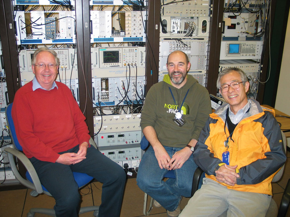 |
| <Figure 1> Ian Gardner and Andy Seville (ISIS/RAL) and Yoshiro Irie (KEK/JPARC) celebrate first beam results with LOI in the ISIS synchrotron, UK. |
Any attempt to accelerate more intense beam faces the difficulties of space charge force and beam loading. In the former case, electro-magnetic interaction between accelerated particles becomes stronger, which causes more particles to deviate from the nominal oscillation pattern. In the latter case, the beam induces more voltage across the cavity gap in the reverse direction to its original accelerating field, resulting in field distortion . These two effects will cause more beam to be lost somewhere in the accelerator. The lost particles activate the accelerator components. Because it is extremely difficult to do maintenance work on these highly activated components, any excessive beam-loss should be avoided. The collaboration aiming to solve these problems started in 1996 with the KEK High Energy Research Organization in Japan, Argonne National Laboratory (ANL) in the USA and ISIS at RAL in the UK <Figs. 2 and 3>.
.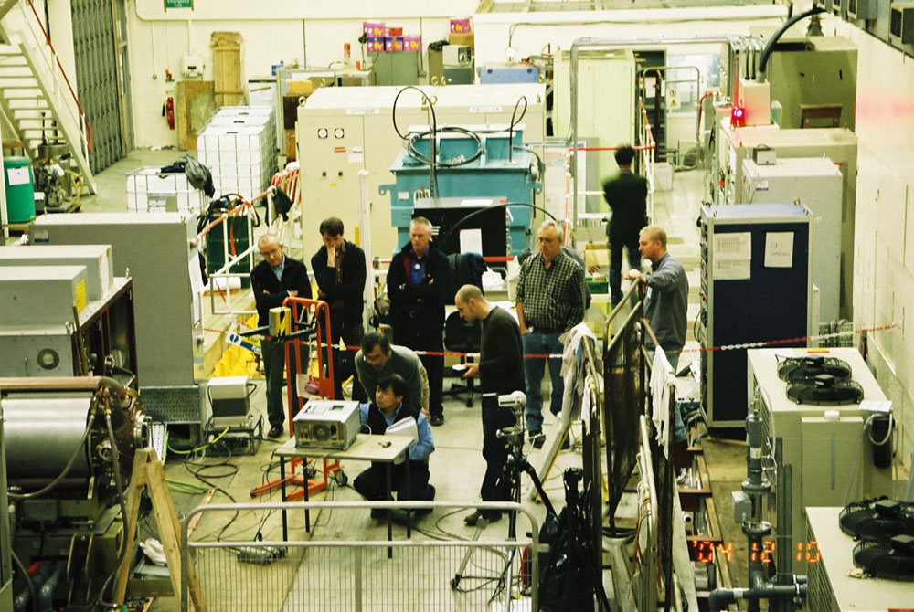 |
| <Figure 2> KEK, ISIS and ANL staff testing LOI equipment at Rutherford Appleton Laboratory. |
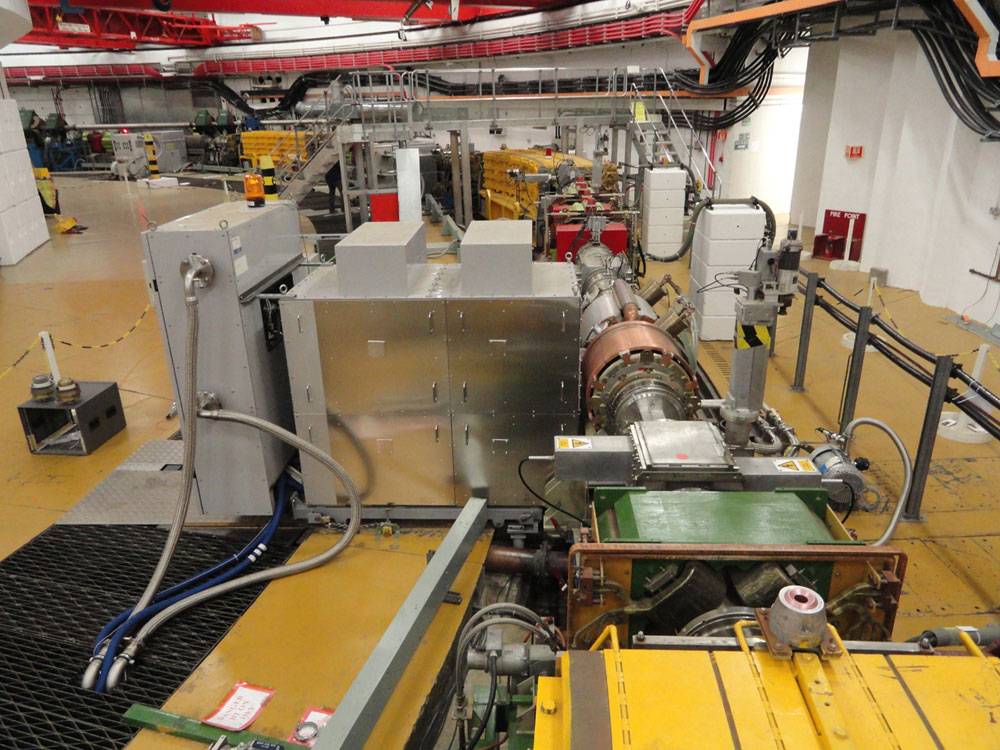 |
| <Figure 3> LOI acceleration system in place at the straight section 6 in the ISIS synchrotron. |
The beam induced voltage across a cavity gap (Vb) is given by Vb = Ib × Zout, where Ib is the circulating current in the synchrotron and Zout the output impedance of the acceleration system. KEK succeeded in developing a low output impedance amplifier with Zout = 35ohms, which is shown schematically in Fig. 4. By choosing an appropriate ratio of the plate-grid impedance (Zpg) to the grid-ground impedance (Zgg), a wideband, high voltage-gain and low output impedance amplifier can be achieved. The beam induced voltage then becomes very small and the beam can be accelerated by the original accelerating field without being affected by beam loading. When this acceleration system is used as the 2nd harmonic cavity system, the beam can be lengthened precisely in a controlled manner along its beam axis. The beam density is then lowered, and the space charge interaction between particles can be alleviated.
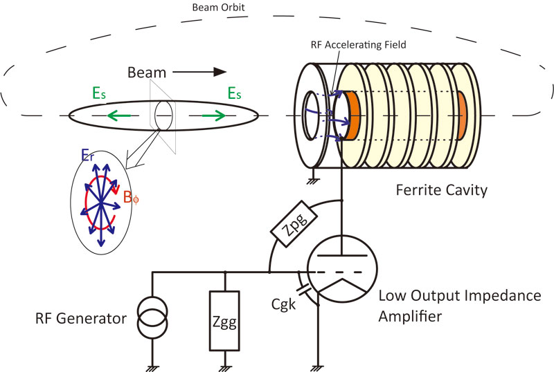 |
| <Figure 4> LOI 2nd harmonic cavity and beam Beam is accelerated by the RF accelerating field and induces the voltage simultaneously at the cavity gap. The space charge force exerted upon a beam having velocity |
Figure 5 shows the beam induced voltage upon the ferrite cavity with and without the LOI amplifier. No sharp peak is seen at 2.16msec for the former case, because the high cavity impedance is shunted by the output impedance of the LOI amplifier. By comparing the voltages at 2.16msec, it is found that the cavity impedance is reduced by 40 times compared with the latter case. With reference to the beam intensity data then taken, the output impedance of the LOI is derived to be 35ohms, which almost agrees with the design value. The LOI voltage envelope and the beam intensity in the synchrotron are shown in Figure 6. It is seen that, by applying the LOI 2nd harmonic system, almost no beam is lost between injection and the end of acceleration and extraction.
In this first experiment, it has been identified that the LOI acceleration system may have the potential to realize very low loss accelerators. Further experiments are planned in near future using beam loss monitors.
References:
(1) For further information,
https://research.kek.jp/group/www-loi/
(2) An article on the first beam experiment is also available at the ISIS website.
https://www.isis.stfc.ac.uk/Pages/Successful-beam-test-on-ISIS-for-new-acceleration-system-after-a-15-year-wait.aspx
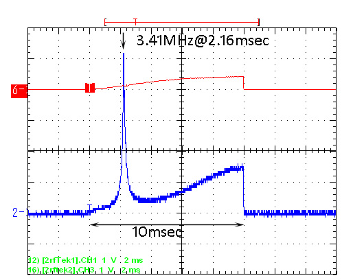 |
| <Figure 5> Comparison of beam induced voltages at the cavity gap with (red) and without (blue) LOI amplifier. |
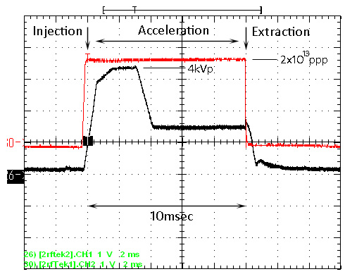 |
| <Figure 6> Beam acceleration test Beam intensity (red) with 2×10¹³ protons peak and LOI voltage envelope (black) with 4kV peak. |
〜 Author : Accelerator Division II, Yoshiro Irie 〜
| Copyright(c) 2008, HIGH ENERGY ACCELERATOR RESEARCH ORGANIZATION, KEK 1-1 Oho, Tsukuba, Ibaraki 305-0801 Japan |
|web-acc |