The concept of the induction synchrotron (IS) was proposed by Takayama and Kishiro in 2000 [1] for the purpose of overcoming the shortcomings, such as a limitation of the longitudinal phase space available for the acceleration of charged particles in a rf synchrotron. Accelerating devices in a conventional synchrotron, such as an rf cavity, were replaced by induction devices in the IS. The acceleration and longitudinal confinement of charged particles are independently achieved with induction step-voltages in the IS, as schematically shown in Fig.1. A long step-voltage generated in the induction acceleration cells gives the acceleration energy. Pulse voltages at both edges of some time-period with the opposite sign, which are generated in other induction accelerating cells, are capable of providing longitudinal focusing forces. These pulse voltages are generated by the master trigger signal made from the bunch signal, which fires the switching power supply (SPS) to drive the induction acceleration cell. Consequently, the acceleration and confinement are synchronized with the beam revolution. The experimental demonstration using the KEK 12GeV PS was divided into three stages: (1) induction acceleration of a single bunch captured by the rf bucket [2], (2) trapping of an injected bunch by the barrier voltages [3], and (3) induction acceleration of the barrier bucket trapped bunch. During the financial year of 2005, the last stage was completed.
The beam-orbit control was the most important issue as well as in any synchrotron. Without this function, charged particles can never be accelerated in a vacuum chamber. The so-called DR-feedback system is equipped to meet this requirement in a conventional rf synchrotron. A similar feedback system [4], where the gate pulse generation was determined by integrating the digital gate pulse generator for the SPS with the orbit information proportional to the momentum error, Dp/p, was introduced in the present IS. When the signal amplitude exceeds a preset threshold value, the gate trigger signal is blocked in the DSP. Accordingly, the acceleration voltage pulse is not generated at the next run and the momentum approaches the correct value, which is uniquely determined by the bending field. An outline of the gate control system is shown in Fig.2.
The experimental results were shown in Fig.3. The top line (green) in the Fig.3 is the DR signal, which is kept to be 2 mm after the starting of acceleration. The beam intensity of the second line (yellow) was lost in the transient region from the injection stage to the parabolic ramping region of the bending field; beyond that the intensity was held to be constant.
Modifying the existing rf synchrotrons to the IS is rather easy, because it is just a matter of replacing the rf devices by the induction devices. In addition, the hybrid synchrotron seems to be very attractive. As a matter of fact, a novel transition crossing method [5], which is called "quasi-adiabatic no-focusing transition crossing", has been developed in the KEK-PS. According to this method, where the rf voltage is linearly reduced to zero at the transition energy and increased to a nominal value, the bunch size is controlled with a desired value. This allows us to avoid any serious problems, such as microwave instability, Johnsen effects, and electron cloud instability, associated with transition crossing in a conventional rf synchrotron
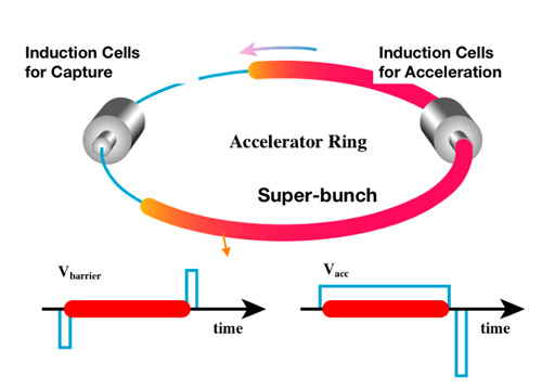 |
| Figure 1 : Schematic view of the induction synchrotron |
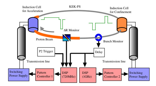 |
| Figure 2 : Schematic view of the IS with the gate control system. The induction systems for the acceleration and confinement are of the same type except, for the gate control, which can generate different voltage-patterns, as shown. P2 means the start of acceleration. The signal monitored at the bunch monitor is employed as a master gate trigger signal for the SPSs. |
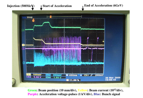 |
| Figure 3 : Typical experimental results |
REFERENCES
[1] K.Takayama and J.Kishiro, Nucl. Inst. Meth. A 451, p304 (2000).
[2] K.Takayama et al., Phys. Rev. Lett. 94, 144801 (2005).
[3] K.Torikai et al., KEK Preprint 2005-80 (2005), submitted to Phys. Rev. ST-AB
[4] K.Torikai, K.Takayama, Y.Shimosaki, J.Kishiro, and Y.Arakida, Patent 2005-198557 in Japan.
[5] Y.Shimosaki, K.Takayama, and K.Torikai, Phys. Rev. Lett. 96, 134801 (2006).
|