|
|
||||||
| >Top >Feature Story >this page | last update:
10/06/16
|
|
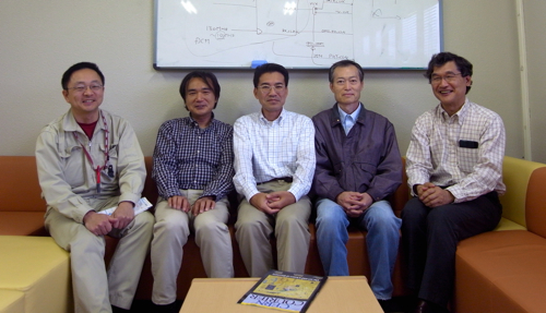
| New network-based DAQ framework may simplify life for scientists The data acquisition system (DAQ) team at KEK’s Detector Technology Project is now offering the particle experiment community a standardized data acquisition system (DAQ) framework of both hardware and software. Learn here about the innovative, network-based readout electronics, and the all-in-one DAQ-Middleware. |
|
|||||||||||||||||
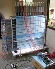
All radiation experiments in Physics use an array of detectors and analysis tools. The detectors sense photons or other particles, and produce the information needed for analysis. Everything that lies in between the detectors and the data analysis tools is part of the data acquisition system (DAQ). Although DAQ systems are not often discussed, they are a key part of many experiments, and often demand significant time and expertise to build. A dream of both the former and current leaders of the DAQ project in the KEK Detector Technology Project (DTP), Dr. Yoshiji Yasu and Dr. Tomohisa Uchida, has been to standardize all necessary components of DAQ systems in order to provide nonprofessional users easy access to high performance DAQ systems. The next-generation DAQ project was the realization of their dream. The innovative feature of their DAQ package is the marriage of the hardware and software components. This is a challenge for DAQ scientists as some of the necessary software tools depend on the type of detectors. The DAQ team developed a complete, general-purpose package of DAQ to be used by scientists of many disciplines who are not necessarily DAQ experts. The scheme has seen many successes since its inception in 2006. Their standardized, fast, and easy-to-use DAQ package has now been installed at many beamlines at the Material and Life Facility (MLF) at the Japan Proton Accelerator Complex (J-PARC) in Tokai, and has many potential applications in other fields of experimental particle physics.
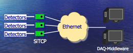
Small, fast, and low-power Tens of thousands of channels of detectors may send signals to a single DAQ. Each channel requires frontend readout electronics, which would transmit a high rate signal to multiple computers. Most experiment utilizes specialized cables for the transmission. At the back end of the DAQ, where PCs analyze the detector data, one would find a TCP/IP network. However, the frontend electronics, where the interfaces to the detectors were located, had no such standardized networking. This, Uchida thought, made flexible data distribution unnecessarily difficult. Uchida’s innovative idea was to employ a network for the frontend electronics. In 2001, he set off to test the principle with a nonstandard network protocol. The use of a nonstandard protocol turned out to be a rather unpopular idea, but the test was a good learning experience. At that time, networks were speeding up rapidly, and the standardized network protocol used for the Internet boosted the network growth worldwide. Uchida traded his nonstandard protocol for Ethernet and TCP/IP, which were and are widely used and therefore much more cost-effective.
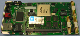
Uchidas solution was to build a highly specialized device, one specifically designed for TCP. To do this, he utilized an application specific integrated circuit (ASIC) implemented on a field programmable gate array (FPGA). Creating a specialized device meant we needed to only include the necessary functions. This decreased the power consumption, and made the device smaller and faster, says Uchida. The key to designing smaller and faster hardware is to make full use of all resources on the device. This means distributing computational tasks as evenly as possible among the process modules on the device so that no modules are ever at rest. To do this, most people would build a controller module onto the chip. However, such a controller requires both additional space and additional power. Thus, Uchida designed his chip without a controller. On his chip, jobs are distributed among process modules by the equivalent of a bucket brigade. This required simple yet sophisticated design, and developing the logic was a challenge. Uchida applied all his skills and experience to this task, and after many test-and-modify cycles, he eventually found the right balance between simplicity and speed.
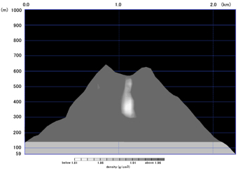
Solar-powered SiTCP for volcano observatory The first experiment to take advantage of the potential of SiTCP is the neutrino observatory Super-Kamiokande. During the readout electronics upgrade in 2008, 500 SiTCP chips were delivered to Kamioka, and installed successfully. Since then, Uchida has worked with many other experiments and detectors. One particularly interesting example is the development of power efficient readout electronics for cosmic-ray muon radiography of volcanoes. Cosmic-ray muon radiography measures the number of cosmic-ray muons that penetrate through a volcano over a period of one month or more. The high-density area of the volcano blocks muons, while low-density area does not interfere with the muon passage. The difference in the number of muons, therefore, provides information about the internal structure of the volcano. One major difficulty encountered when building an observatory near a volcano is that access to commercial power sources is generally limited.
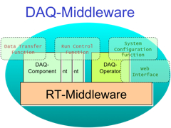
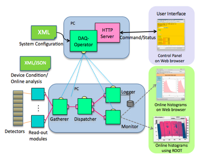
Uchida, in collaboration with colleagues at the Earthquake Research Institute at the University of Tokyo, developed low-power readout electronics with a wireless LAN capability which could be powered by solar energy. The system has since been used to observe several volcanoes in Japan. Other successful applications of SiTCP technology include electronics for the Hyper Suprime-Cam for the Subaru Telescope at the summit of Mauna Kea, Hawaii. Uchida has also worked with other advanced detectors such as the gas electron multiplier (GEM) and the silicon-on-insulator (SOI) board that other projects in the KEK DTP develop. User-friendly, versatile DAQ middleware Alongside the small, fast, power efficient readout electronics, the DAQ team has also focused on the backend software. Tens of thousands of channels of data, each having a transfer rate of one-gigabit per second, need to be distributed efficiently throughout the system. The DAQ team’s new middleware, called DAQ-Middleware, unites all the required software components in one place. These components gather data, distribute data, build events, and analyze the data acquired by the detectors, with a user interface in a standard web browser.
Yasu finally saw an opportunity when he heard about the robot technology middleware (RT-Middleware) software, which is specified by international standard. A software package for the RT-Middleware is developed at the National Institute of Advanced Industrial Science and Technology (AIST) in Tsukuba. The RT-Middleware software was developed not only for robot system but also for an embedded system. An embedded system has devices with sensors, readout electronics, and software to process, analyze, and store data, says Yasu. The framework was just what I was looking for. Yasu proposed developing the DAQ-Middleware for the 2006-2008 next-generation DAQ project, and started developing DAQ specific tools to be implemented in the RT-Middleware framework, in collaboration with colleagues at KEK and AIST.
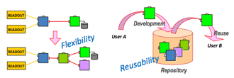
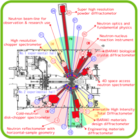
The first two years of the project were spent on basic research, and on developing the pre-prototype. In 2008, the prototype was installed in a neutron beamline at J-PARC, and was tested at the first beam commissioning. After a year-long debugging period, the DAQ-Middleware was installed at another neutron beamline in 2009. The installation was without trouble, and the system was immediately successful, surprising everyone at the beamline, who were all familiar with the pains of DAQ systems in general. Now, at the Material and Life Facility (MLF) at J-PARC, over half of the twenty-three neutron beamlines and one muon beamline either have installed, or plan to install, the DAQ-Middleware. Reusable repository and easy installation For Yasu and his team members, challenges still remain. First, one objective is to make the DAQ-Component reusable from experiments to experiments. For example, the DAQ-Middleware depends on the software framework specification developed at the MLF according to their requirements. The DAQ-Middleware repository for such experiment-specific frameworks still needs improvements before it can be used in projects beyond MLF.
A complete DAQ package The team is united in their desire to create a versatile, user-friendly DAQ-Middleware. “The DAQ-Middleware is a new foundation for DAQ,” says team member Eiji Inoue. For the new DAQ-Middleware project leader, Kazuo Nakayoshi, the system is in the process of developing into a broader and more complete DAQ system, one which can easily be used in many different types of experiments. “The inter-university network for collaborative development of the complete DAQ-Middleware is growing right now,” says he. “We hope to make good use of this opportunity for the continued improvement of the DAQ system.”
Meanwhile, Uchida is continuing to improve the SiTCP hardware. This year, the SiTCP FPGA chips will become capable of processing data at a rate of ten gigabit per second. His other current project is clock synchronization using networks. For proper job distribution among networked computing resources, the system clocks of every computer in the network need to be synchronized. Generally, the time is defined by a nest of clock systems, which is itself extremely complicated. “Now that the readout electronics are on a network, we can talk about synchronizing clocks using a network clock,” says Uchida. This is not a straightforward job. Networks have jitter, and the arrival time of a packet can vary. Uchida is investigating possibilities to work around this difficulty. The complete package of DAQ for particle experiments and observatories, with installation tools and full documentation, is now available, and will be a great benefit to scientists of many disciplines. |
| copyright (c) 2010, HIGH ENERGY ACCELERATOR RESEARCH ORGANIZATION, KEK 1-1 Oho, Tsukuba, Ibaraki 305-0801 Japan |
||