The Accelerator
A high energy electron or positron emits synchrotron light when forced to turn and loses its energy. The center of mass energy of a storage-ring-type e
+e
- collider is practically limited to around 200 GeV, e.g. LEP at CERN, due to this energy loss. Exploration into TeV energy region with e
+e
- collisions thus requires development of a new collider concept, a linear collider and not a ring-type collider.
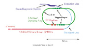 |
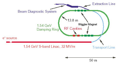
Schematic View of the ATF
|
The major component of the JLC is a pair of very long, powerful linear accelerators called main linacs, one for electron and the other for positron. The accelerated beams of electrons and positrons are then focused into a nanometer-size spot in the interaction region and are brought into collisions at physicists' disposal.
A minimum attainable beam size at the interaction point is determined only by the initial beam emittance which is one of the most important beam parameters that defines the beam quality. Therefore it is essentially important to produce a high quality beam at the initial stage of acceleration. Such a beam can be obtained by storing it in a ring called a damping ring, where the beam emittance is reduced due to the mechanism of synchrotron radiation damping.
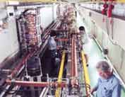 |
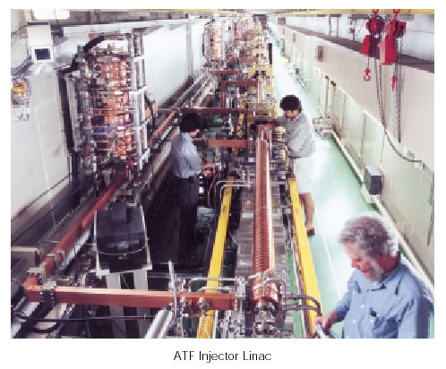
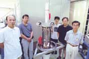
ATF Injector Linac
|
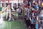 |
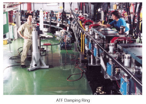
ATF Damping Ring
|
To experimentally confirm its feasibility, we have constructed a large scale Accelerator Test Facility (ATF) at KEK. The ATF consists of two major components: an S-band injector linac and a damping ring.
The injector linac consists of a conventional thermionic gun, a sub-harmonic buncher, an Sband buncher and eighteen 3m-long S-band accelerating structures with constant acceleration gradient. The overall length of the linac is 75 m. The compressed pulse from a high power RF source, an 80 MW klystron, is divided into two and are fed to two accelerating structures. The average accelerating gradient is designed to be 32 MV/m with beam loading.
For achieving ultra-low emittance, the arc sections of the damping ring have a special lattice structure of FOBO type in which a focusing quadrapole (F) and a defocusing bend (B) are placed at the minimum point of dispersion.
The commissioning of the ATF began in early 1997. Since then, various improvements have been made to achieve the stable operation of the ATF. In November 1997 the extraction line from the damping ring became available for detailed beam diagnostics. The design goal on the beam emittance has almost been met in a single-bunch mode; the horizontal and vertical emittance are about 2 × 10
−9 meter rad and 1~2 × 10
−11 meter rad at 10
10 electrons/bunch. It is worth mentioning that the performance of the ATF has also encouraged people working on linear colliders such as CLIC (the Compact LInear Collider at CERN) in which beam-emittance should be even lower.
The RF system for the main linacs is one of the most important components to be newly developed for reaching into the TeV energy region. Considering the potentially higher acceleration gradient and efficiency, X-band (11.4GHz) was chosen as the best frequency for the RF system of the JLC, and C-band (5.7GHz) as its backup option. The X-band is four times higher than the S-band which is employed for many existing linacs. This big jump in frequency implies a technological challenge, and necessitates a systematic and time-consuming R&D.
In order to make maximum use of resources available in the world, the X-band R&D has been carried out in close collaboration with Stanford Linear Accelerator Center and the Protvino branch of Budker Institute of Nuclear Physics. The collaboration led us to deeper understanding of the behaviors of the X-band RF system and resulted in the first prototype klystron successfully tested in the FY 2000. The most recent model has been producing 73 MW output power with a 1.4 microsec pulse width, nearly satisfying the JLC specification.
 |
X-band Klystron
|
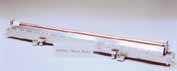 |
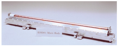
X-band Accelerating Structure
|
Another important element in the RF system is an accelerating structure, which usually consists of a stack of disks. Because of the shorter wavelength of the X-band, the accelerating structure becomes much more compact than that of the S-band system. The hind side of this merit is the mechanical tolerance that is much tighter, thereby calling for a new method to construct a high quality structure with high precision.
The latest design of the structure requires the disks to be machined to 1 micron precision and to be aligned to better than 5 µm precision over the whole length of 1.8 m. The KEK team has established the technology to meet the requirements and the constructed prototype structures have fulfilled the tolerance specifications.
The JLC is a huge accelerator complex and there are many activities for each component R&D far more than listed in here. The R&D on essential components of the whole accelerator system has been nearly completed. We are finalizing the conceptual design of the JLC through the integration of our cumulative R&D efforts and resultant advance in accelerator physics.