
Font size 

Advanced Studies

Accl. Operations

Past Accl. Operations
Accelerator R&D

Theoretical Research
Archives
Minuscule Gremlins Cause Vacuum Breakdown
in Radio-Frequency Accelerating Cavities
Radio-frequency (RF) accelerating cavities (hereinafter referred to simply as RF cavities) are at the heart of many modern particle accelerators. An RF cavity is a metal resonator that can store high-energy microwaves to accelerate charged particles by the high-electric field of the stored microwaves. RF cavities are roughly divided into two types: super-conducting RF cavities (made of pure niobium, operated at very low temperatures) and normal-conducting RF cavities (made of pure copper, operated at room temperature). The present article addresses only normal-conducting RF cavities, which are hereinafter referred to simply as cavities.
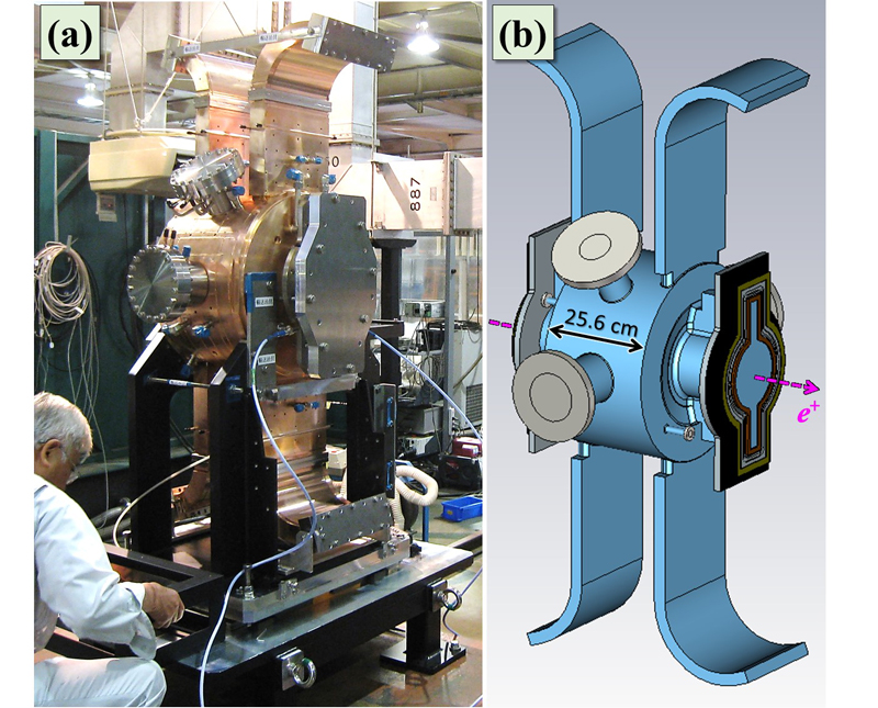 |
| < Figure 1 > RF accelerating cavity for the SuperKEKB positron damping ring (DR). (a) Photograph of DR cavity No. 0 taken immediately after its delivery. (b) Schematic diagram of the cavity. The blue region is an ultrahigh vacuum during high-power operation. The magenta arrow indicates the beam axis, and positrons (e+) accelerate inside the 25.6-cm gap. |
Figure 1 shows the cavity used in the present study, which was developed for the SuperKEKB positron damping ring (DR) accelerator (for details, see Accl. Lab. Topics 2013/10/7). The inside of this cavity was made for resonantly storing 509-MHz microwaves and is a vacuum of 10-6 to 10-5 Pa during high-power operation. High-power microwaves of one hundred tens of kilowatts are continually fed into this cavity to excite a high electric field to accelerate positrons moving along the central beam axis (magenta arrow in Figure 1(b)). Figure 2 shows the excited electromagnetic field. Positrons are “kicked” by the high electric field shown in Figure 2(a) for acceleration.
 |
|
| < Figure 2 > Electromagnetic field for acceleration (TM010 mode). The phase of the field is synchronized between (a) and (b). | |
RF cavities have a higher performance if they can accelerate beam particles with a higher accelerating field (accelerating gradient). However, a higher accelerating field causes more vacuum arcs in a cavity, followed by vacuum breakdown, resulting in cavities no longer accelerating beam particles, which can limit the accelerator performance. Therefore, the important characteristics for cavities to have are a high accelerating field in combination with a low breakdown rate. In the case of this cavity, the maximum surface electric-field strength during high-power operation is approximately 10 MV/m (= 10×106 V/m), which is two orders of magnitude lower than that required for field evaporation (several GV/m; 1 GV/m = 109 V/m). However, vacuum breakdowns occur during high-power operation.
Field evaporation is a phenomenon whereby metal surface atoms are ionized and detached by a strong electric field applied to the surface. Therefore, an accelerating-field strength that is sufficient to cause field evaporation is an ultimate limit in normal-conducting RF acceleration. Vacuum breakdowns of this cavity were observed at much lower field strengths, which means that such breakdowns occurred by a mechanism other than field evaporation. Elucidation of the breakdown trigger mechanism is of intrinsic importance in normal-conducting RF acceleration technology. However, although numerous breakdown studies have been performed by numerous researchers around the world, the mechanism remains unclear. If “seeds” of the breakdown trigger mechanism are so minuscule, then the information they contain can be mostly destroyed by the much larger phenomenon of the vacuum arc. Understanding this mechanism is difficult, even if we collect numerous observables, as obtained in traditional breakdown studies, such as reflected microwaves, X-rays, current flashes, and acoustic emissions, which are all results of vacuum arcing.
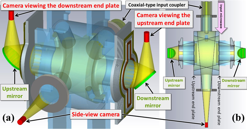 |
| < Figure 3 > (a) Schematic diagram of the setup of the three cameras (red cylinders). The yellow conical regions represent the fields of view of the cameras. (b) Cross-section along the horizontal plane including the center of the cavity. |
In 2014, we performed an experimental breakdown based on direct in-situ observation of the inside of this cavity, with the setup shown in Figure 3. This study was guided by the conviction that a "direct" picture is worth a thousand "indirect" measurements, and we demonstrated for the first time the usefulness of the direct in-situ observation method (for details, see Accl. Lab. Topics 2016/10/5). Even if the information related to the breakdown trigger mechanism is completely destroyed by a huge vacuum arc, we could directly see the seed of the breakdown trigger in the recorded image at the moment of breakdown. From this observation, we discovered that pyrotechnical breakdown events, such as lightning, as we imagine from terms related to vacuum arc and breakdown, are minor (only 10%). Major breakdown events (approximately 65%), which are classified into two types, are quiet. The first type is accompanied by a small explosion of a stable bright spot on one of the two end plates of the cavity; prior to the explosion, this bright spot was observed to maintain its intensity for hours or longer with no significant effects on the accelerating field during high-power operation (Breakdown Type I). An example of a Breakdown Type I event is shown in Figure 4. The other type is accompanied by a spot-type (i.e., localized) small explosion that does not originate from a stable bright spot (Breakdown Type II). An example of a Breakdown Type II event is shown in Figure 5. However, this observation could not clarify (1) what the stable bright spots of Breakdown Type I were or (2) the generation mechanism of spot-type explosions of Breakdown Type II.
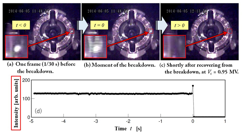 |
| < Figure 4 > Example of a Breakdown Type I event. (a)–(c) Snapshots of the upstream end plate, in chronological order, at a cavity voltage (Vc) of 0.95 MV. The insets in (a)–(c) are magnified views of the region outlined by the red square. (d) Temporal evolution of the intensity of the region outlined by the red square, where the origin of the horizontal axis is the time at which this breakdown occurred, as shown in (b). Download link for the video file. |
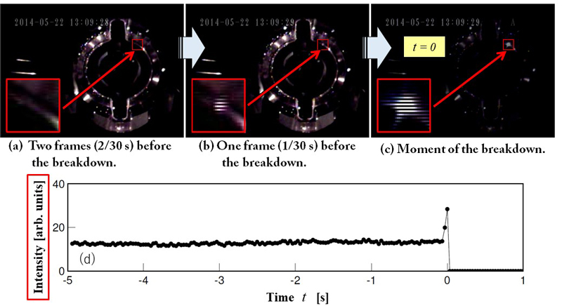 |
| < Figure 5 > Example of a Breakdown Type II event. (a)–(c) Snapshots of the upstream end plate, in chronological order, at a cavity voltage of 0.56 MV. The insets in (a)–(c) are magnified views of the region outlined by the red square. (d) Temporal evolution of the intensity of the region outlined by the red square, where the origin of the horizontal axis is the time at which this breakdown occurred, as shown in (c). Download link for the video file. |
In order to investigate the light emitters of stable bright spots in Breakdown Type I, we performed an advanced direct in-situ observation in 2017 using a hyperspectral camera, and succeeded for the first time in measuring the emission spectra. As a result, the stable bright spots were found to be thermal radiation for temperatures higher than 1000 ºC. The results of the temperature measurement are shown in Figure 6. Considering the fact that the inside of the cavity was an ultrahigh vacuum of approximately 10-5 Pa, the emitter of the stable bright spots cannot be copper (the base material) and should be a material with a high melting point, such as carbon, molybdenum, tantalum, or tungsten. The light emitters are considered to have been heated by surface current and/or field emission associated with the accelerating field. However, the constituent elements of the light emitters were not identified this time. Moreover, some mechanisms related to stable bright spots remain unexplained, specifically regarding the heat generation required to reach the observed high temperatures, the disruption of their stability, and the explosion.
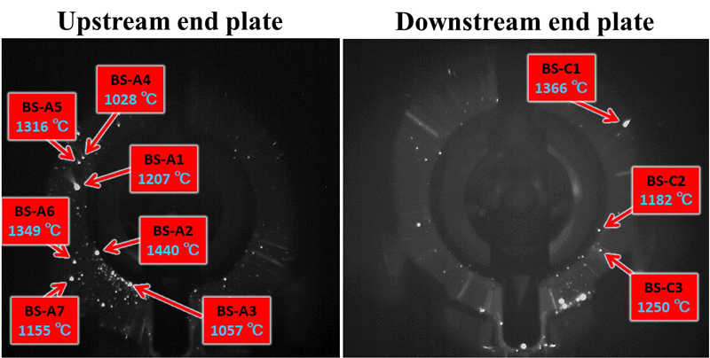 |
| < Figure 6 > Results of the temperature measurement for ten stable bright spots at a cavity voltage of 0.95 MV obtained by measuring the emission spectra in the 700- to 800-nm wavelength region. The average temperature of the cavity surface during high-power operation was around 40 or 50 ºC. |
In addition to the spectrum measurement, we made novel direct in-situ observation of breakdown events using three high-speed cameras with a frame rate of 1000 or 2000 frames per second (fps). As a result, we observed strange breakdown events, out of a total of 40 detected events, which were accompanied by a flying bright object impacting the end-plate surface and triggering breakdown. A video of one of the four strange breakdown events is shown in Figure 7. This kind of event was observed in RF cavities for the first time. In the previous direct in-situ observation performed in 2014, we used less-advanced video cameras at 30 fps, so that such strange breakdown events might be observed as being accompanied by a spot-type explosion that did not originate from a stable bright spot. Although we did not measure the temperatures of the flying bright objects, they are expected to be high, similar to those of the stable bright spots of Breakdown Type I because, despite traveling at a low speed on the order of 10 m/s, the flying bright objects caused an explosion on the end-plate surface. Breakdown Type II events can be understood as a physical process in which a “hot” charged microparticle accelerates and impacts the end-plate surface, leading to an explosion on the surface which ignites a vacuum arc.
| < Figure 7 > Slow motion video (slowed 200 times) of one of the strange breakdown events accompanied by a flying bright object impacting the end-plate surface. A flying bright object appeared near the downstream end plate (right image), moving upstream, and impacted the upstream end plate (left image) at t = 0.081 s. Breakdown occurred at the moment of impact (t = 0.081 s). This video was recorded with three high-speed cameras synchronized during high-power operation. |
These new direct in-situ observations have advanced our understanding of the breakdown trigger mechanism, revealing that “minuscule gremlins” cause vacuum breakdown in normal-conducting RF cavities. These results have recently been published in the scientific journal Physical Review Accelerators and Beams [3]. In the future, we intend to (1) identify the elements of light emitters of stable bright spots and (2) conduct further direct in-situ observations using even higher-specification cameras. Such advanced observations might clarify the nature of these minuscule gremlins. The cavity explained in this article is operated with continuous microwaves in the ultrahigh frequency band. We intend to investigate whether such gremlins exist in normal-conducting high-gradient accelerating structures operated with pulsed microwaves at higher frequency bands based on the direct in-situ observation method.
This work was supported by Grant-in-Aid for Scientific Research (JSPS KAKENHI, Grant No. 15H03671), and by the support service of the KEK Mechanical Engineering Center.
References (scientific presentations and papers)
[1] T. Abe, "Updated Results of Breakdown Study for 509-MHz Continuous-Wave Accelerating Cavities based on Direct In-situ Observation", presented at the 7th International Workshop on Mechanisms of Vacuum Arcs (MeVArc 2018), Puerto Rico, May 20-24, 2018 (web page containing the presentation file).
[2] T. Abe, T. Kageyama, H. Sakai, Y. Takeuchi, and K. Yoshino, “Experimental RF Breakdown Study based on Direct In-situ Observation of Normal-Conducting Accelerating Cavities”, presented at the 15th Annual Meeting of Particle Accelerator Society of Japan (PASJ 2018), WEOL01, Nagaoka, August 7-10, 2018, WEOL01 (Download link of the complete version of the paper).
[3] T. Abe, T. Kageyama, H. Sakai, Y. Takeuchi, and K. Yoshino, “Direct Observation of Breakdown Trigger Seeds in a Normal-Conducting RF Accelerating Cavity”, Physical Review Accelerators and Beams 21, 122002 (2018).
- Author: Accelerator Division III, Tetsuo ABE -
| Copyright(c) 2008, HIGH ENERGY ACCELERATOR RESEARCH ORGANIZATION, KEK 1-1 Oho, Tsukuba, Ibaraki 305-0801 Japan |
|web-acc |