Successful Excitation Test of High Luminosity LHC Upgrade Superconducting Magnet "D1" Prototype
(English translation 2022-11-14)
LHC accelerator at the European Organization for Nuclear Research (CERN) is known for the discovery of the Higgs boson particle (Nobel Prize in Physics 2013). High-Luminosity LHC Upgrade (HL-LHC) project is underway at CERN to further the search for new physics. Universities and research institutes around the world, including KEK, are participating in HL-LHC project. As introduced in our previous highlight ‘International Contribution to High Luminosity LHC Upgrade with Large Aperture Beam Separation Superconducting Dipole Magnets’ , KEK has been developing the superconducting magnet D1 for HL-LHC. Figure 1 shows a cross-sectional schematic view of the magnet and superconducting coil. After the successful development of 2-meter-long model magnets to verify the design and fabrication method, the fabrication of a 7-meter-long full-scale prototype magnet MBXFP1 has been underway since 2020. In June 2021, the excitation test at 1.9 K was finally started (Figure 2). The details of the process up to this point are reported in the introductory article: 'Performance evaluation of the superconducting magnet "D1" prototype for High-Luminosity LHC Upgrade has started!' .
It is particularly important for accelerator superconducting magnets to ensure that the magnet can be energized stably and that the magnetic field is correctly generated as designed (i.e., that the field error is sufficiently small). In addition, the superconducting coils must be safely protected in case of a sudden transition from superconducting to normal conducting state (i.e., “quench”). As a result of various tests including excitation tests, the D1 prototype has proven to have good performance that fully satisfies the specifications of HL-LHC accelerator. Based on these results, we finally started a series production of the D1 magnet in December 2021. A total of six D1 production magnets, including spares, will be manufactured for installation in HL-LHC accelerator starting in 2026, and these production magnets will be delivered to CERN as Japanese in-kind contribution.
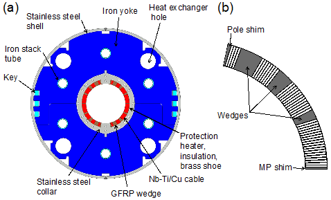
Cross-sectional schematic view of D1 magnet (a) and superconducting coil (b)
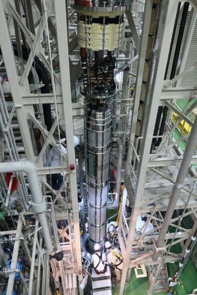
MBXFP1, a 7-meter-long full-scale D1 prototype magnet being inserted into a 1.9 K cryostat
Below we present some examples of excitation test results from our D1 prototype magnet.
To use a superconducting magnet in a beam accelerator, it is firstly important that the magnet can be energized stably. In the case of D1 magnet, a magnetic field of 5.6 T is generated at a rated current of 12,110 A to bend (kick) a 7 TeV proton beam passing through a 150 mm diameter space. The electromagnetic force on the superconducting coils then reaches 160 tons per meter. Since the superconducting coils alone cannot withstand such a strong electromagnetic force, the coil is designed to be mechanically supported by an iron and stainless-steel structure, as shown in Figure 1(a). If the support is inadequate, the coil will be deformed during excitation, and the resulting friction will be converted into heat, leading to a local temperature increase. The niobium-titanium superconductor will then make transition from superconducting to normal conducting state and will no longer be able to conduct high currents. This phenomenon is called a "quench". In the excitation test, the current-carrying capacity of a superconducting magnet is evaluated by the following indexes.
- The target current should be reached in a small number of quenches.
- The final maximum current achieved should be as high as possible.
- The quench current should not decrease during the test.
- The magnet should be able to energize stably in the second excitation test after the full thermal cycle to room temperature.
Figure 3 shows the results of the quench test. The horizontal axis is the number of quenches, and the vertical axis is the quench current. In the quench test, the current is increased at a constant ramp rate from 0 A, and the current circuit is shut down instantly upon detection of a quench signal (normal conduction transition = voltage signal associated with resistance generation). This series of energization tests is repeated to investigate the relationship between the number of quenches and the quench current. In Figure 3, the results of the MBXFP1 prototype are plotted on the far right. For comparison, the test results of the previously developed 2-meter models (MBXFS-1, -1b, -2, and -3) are also shown. The reference horizontal lines indicate the nominal current (I-nominal) and target current (I-ultimate, equivalent to 108% of the nominal current). In the first test cycle of the MBXFP1 prototype, the nominal current was reached after the fourth excitation. According to the fact that the current increased without decreasing from the initial quench current, the good training behavior* was also confirmed. The magnet showed the same training characteristics in the second test cycle, after the magnet was warmed up to room temperature (thermal cycle, TC), as the first test cycle. The quench current reached a maximum of 12,866 A, but due to the limitations of the test facility, no higher current could be energized. Finally, the test was completed after confirming stable energization for more than 4 hours at 105% of nominal current. During the excitation tests, the quench current did not decrease, indicating very stable energizing performance.
* Behavior seen in good superconducting magnets, where the magnet can be energized stably up to the current experienced once, and the attained current increases each time the magnet is energized.
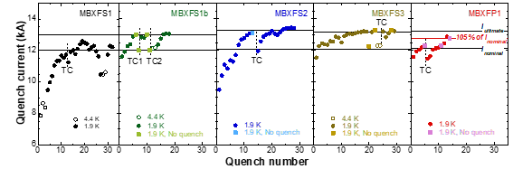
Training quench test results for the 7-meter long D1 prototype, MBXFP1.
For comparison, results for the previous 2-meter model magnets (MBXFS-1, 1b, 2, and 3) are also shown.
For superconducting magnets used in accelerators, the magnetic field characteristics are as important as the excitation stability. The magnetic field must be generated as designed, which means that the field error must be small enough. Generally, the magnetic field generated by a magnet is expressed as a superposition of multi-pole magnetic fields (dipole, quadrupole, sextupole, ..., 2N-pole magnetic field). For example, D1 magnet is a dipole magnet for bending beams, so the main magnetic field consists of N and S poles, but quadrupoles or higher order multipoles also exist as unnecessary magnetic field error. This unwanted field error is a problem. At LHC, the proton beam travels around the 27 km long accelerator ring at nearly the speed of light. The proton beam must keep a stable orbit for several hours during beam collision experiments. For this reason, each of the accelerator's magnets (dipole and quadrupole magnets) is aimed to suppress the field error to less than 1/10000 of the main magnetic field. If the field error exceeds the allowable value, the orbit will become unstable and the beam will be deviated in an unexpected direction, making it impossible to continue the experiment. In addition, the lost beam will always hit the beam duct or magnet, which will cause their radioactivation, leading to equipment failure and shortening the life of the equipment.
Figure 4 shows the measurement results of the sextupole component (b3) as an example of the magnetic field measurement of D1 magnet prototype. The horizontal axis is the magnet current. In the case of a dipole magnet, the largest field error is the sextupole component, so the performance of the dipole magnet can determined by how small the sextupole component can be suppressed. Figure 4 shows that the sextupole component fluctuates up and down as the current increases. In the low current region below 3,000 A, the hysteresis depends on the current history due to a phenomenon called "screening current," which is unique to Type-II superconductors. As the current is further increased, above 6,000 A, we observe the saturation of the permeability of the iron yoke and the effect of coil deformation due to electromagnetic forces. These current dependencies must be fully considered to keep the sextupole component below the permissible value. In fact, in the previous model magnets (MBXFS-2 and -3), the sextupole component reached +36 units (1 unit corresponds to 1/10000 of the strength of the main magnetic field, i.e., dipole field), which greatly exceeded the permissible value, due to a problem in the design. The cross-sectional arrangement of the superconducting coils was redesigned in the prototype, and as shown in Fig. 4, we succeeded in reducing the sextupole component to -8 units. It should be noted that the results obtained this time include the effect of the test environment (in this case, the effect of saturation of the permeability of the surrounding iron). In the actual operating environment of HL-LHC, the sextupole component is expected to be further reduced to the equivalent of -2 units due to the different iron arrangement.
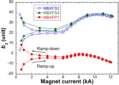
Magnetic field measurement results of the 7-meter long full-scale D1 prototype MBXFP1, showing the current dependence of the sextupole component (b3).
As described above, we have confirmed that D1 prototype magnet has the performance required for HL-LHC accelerator. The magnetic field performance of the series production magnet will be further improved by fine-tuning the cross-sectional shape of the wedges and shims shown in Fig. 1(b) in steps of 10 microns.
Reference sites
- International Contribution to High Luminosity LHC Upgrade with Large Aperture Beam Separation Superconducting Dipole Magnets (ARL Highlights) (in Japanese)
- Performance evaluation of the superconducting magnet "D1" prototype for High-Luminosity LHC Upgrade has started! (KEK Institute of Particle and Nuclear Studies) (in Japanese)
- KEK and CERN Sign Agreement on Cooperation at HL-LHC (KEK Newsroom) (in Japanese)
- High-Luminosity LHC | CERN (CERN)
- High Luminosity LHC Project (CERN)
- LHC/ATLAS Experiment (Japan Group Website) (in Japanese)